FiberWatcher
FiberWatcher Intelligent Optical Cable Network Monitoring and Management System
1.Executive Summary
1.1 Introduction
We are pleased to present a unique solution called FiberWatcher. Our solution, FiberWatcher, is deployed at operators and service providers, helping them to identify fiber optical areas for improvement. FiberWatcher has had a positive impact to the bottom line of each of our customer’s internal processes and revenue. Using FiberWatcher our customers can:
●Assure network quality
●Test new services
●Quickly identify and fix faults
●Foresee fiber degradation
In addition to this proposal, ShinewayTech will be presenting further details of our solution and explore how we can be of assistance in SHINEWAYTECH.
1.2 Solution Summary
1.2.1 Advantages of the FiberWatcher Solution
To summarize, the proposed solution from ShinewayTech offers the following advantages:
●Expand the system to accommodate in-service monitoring system.
●Modular and hot-swap hardware design to reduce the maintenance cost.
●Up to 128 optical ports on the RTU, and up to 384 optical ports with an external OTAU.
●Easy web interface access.
FiberWatcher Remote Fiber Test System is an intelligent system developed to meet the requirements of maintaining and managing a optical fiber network. It is powerful in function, convenient to operate, strong in expandability and easy to install and maintain.
Besides performing 24-hour monitoring over the optical fiber network to get detail optical fiber information and locate faults, FiberWatcher provides varieties of testing modes for active or dark fiber and on-demand or scheduled test.
In addition to the varieties of testing and analyzing functions, Geographic Information System (GIS) interface, and optical fiber testing and alarm locating, FiberWatcher is also able to provide management and statistical analysis of resources in the optical fiber network by combining the powerful functions of Oracle database. Therefore, it can help senior managers comprehensively master the status of the optical fiber network and intelligently make relevant decisions.
With the design of embedded operation system and compact module, FiberWatcher is highly stable and convenient to expand and maintain. FiberWatcher offer a complete, stable, and powerful fiber testing system to shorten the optical fiber’s fault time and improve the QoS.
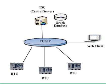
1.2.2 Test System Controller (TSC)
TSC is the data collection and analysis center of FiberWatcher, and is also the management center of the whole monitoring system. The TSC central monitoring station can manage and test all Remote Test Units (RTU). In order to facilitate the operations of maintenance, TSC also provides remote access and onsite monitoring platforms. Each TSC can monitor the optical fiber status and is also able to designate testing and statistics. The operator can adjust the system settings according to specific requirements.
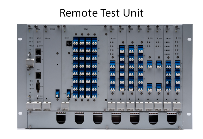
1.2.3 Remote Test Unit (RTU)
Remote Test Unit is a monitoring device integrating with hot-swap controller, optional redundant power module, OTDR, optical switch, WDM/filter, optical power meter, and powerful system software.
RTU can be flexibly configured with different hardware modules to meet various monitoring purposes. RTU can conduct 24-hour monitoring of optical fibers and record data for comparison of reference parameters. When a fault occurs, RTU will automatically analyze and feed back to TSC. Meanwhile staff can perform relevant testing and maintenance for the RTU through TSC.
The optical switch ports are connected to individual fibers for measurement. The OPM can measure the periodical optical power attenuation and foresee the degradation.
●High stability – embedded operation system
●Complete system functionalities – modular hardware for various test purpose
●Monitor module status, version, serial number, and production date from TSC
●Module working voltage detection
●Send alarm message to TSC when module failure
●Modular and hot-swap hardware design reduce mean time to repair
●Redundant VDC input
●Dry contact for alarm output
●Real-time monitoring with optical power meter (OPM)
●Audible alarm and alarm cut off (OPM)
●Maximum 128 ports per chassis, expandable to 384 ports in external chassis
●Upgrade RTU operation system, application software and backup data remotely
1.2.4 Optical Test Access Unit (OTAU)
The OTAU is second tier of RTU, and thru OTAR the user can switch the test fiber link remotely. OTAU integrates the master control unit, power module, optical switch, WDM/filter, and optical power meter.
1.2.5 Communication Network
FiberWatcher uses TCP/IP as its main communication protocol.
Remote Test Unit (RTU) has a RS-232 interface and the TELNET network interface of CIT (Craft Interface Terminal) control solution, facilitating the project staff check of the complete device status; RTU can connect with network management center via IP network; when data communication using TCP / IP protocol, to ensure the network devices’ communication. It supports concurrent TCP connections and supports multiple simultaneous alarms.
1.2.6 System Platforms
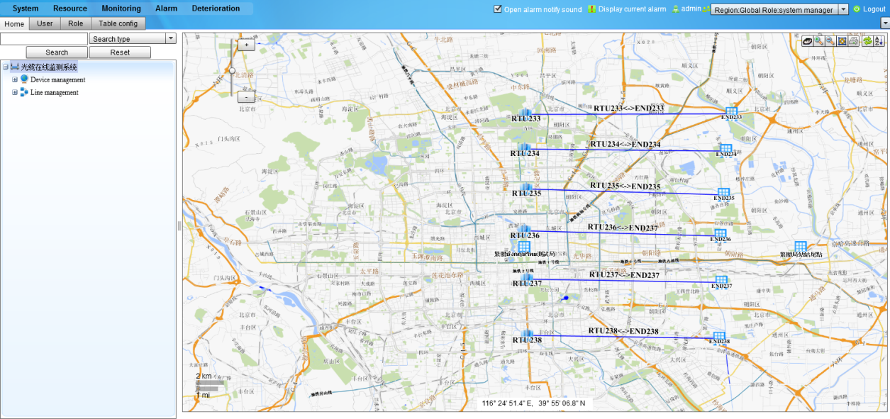
●GIS (Geographic Information System)
●Database - Oracle 10g
●Operation System
server: Windows 2003/2008
client: Windows XP
1.2.7 System Features
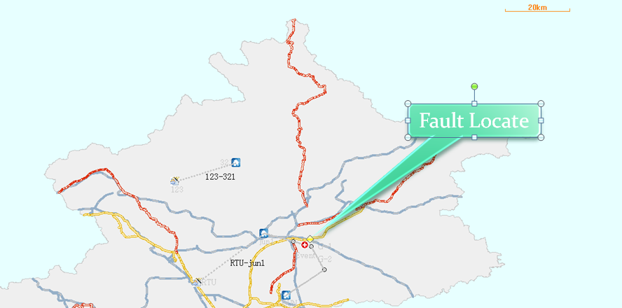
●Integrated with Geographic Information System (GIS) – faults locating on GUI
●Various kinds of alarm – blinking fiber icon, e-mail, SMS, and audible voice
●Friendly Web-based Graphic User Interface
●Authorized administration area of RTU and fiber
●Remote on-line and off-line fiber monitoring
●Fiber degradations analysis
●Optical light source and optical power meter perform 24-hour real-time fiber alarm monitoring
●Manual and scheduled test
●Alarm threshold setting
●Powerful and efficient Oracle database
●Open interface – SNMP and CORBA
1.2.8 System Functionalities
●Graphic User Interface
• Faults locating, resource, equipment and customer information management in GUI
• Selectable Layer Maps
●System Management
• User Management
• Log Management
• User Area Management
●User’s properties edit, modify and query
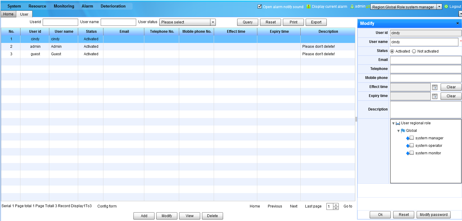
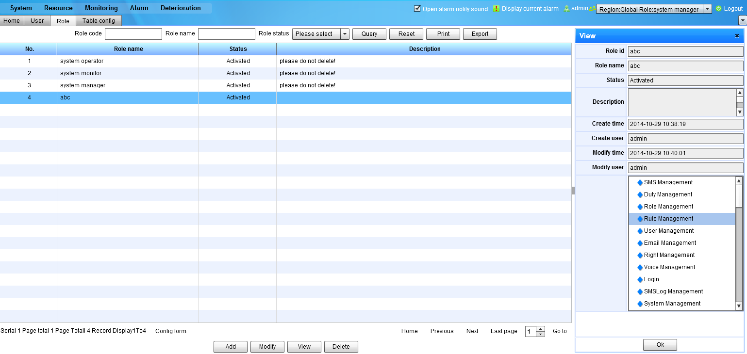
● Authority Management
• Role Management
• Role Authority Management
• Menu Sorting
●Different accounts assigned to different role with different authorization
●Resource Management
• Monitoring Center Management
• Fiber Cable Management
• Fiber Core Management
• Site Management
• RTU Management
• Geomark Management
• Equipment Management
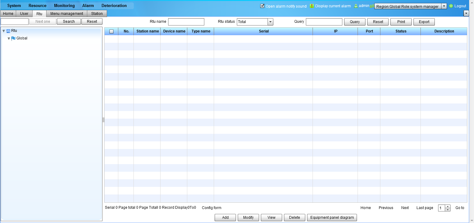
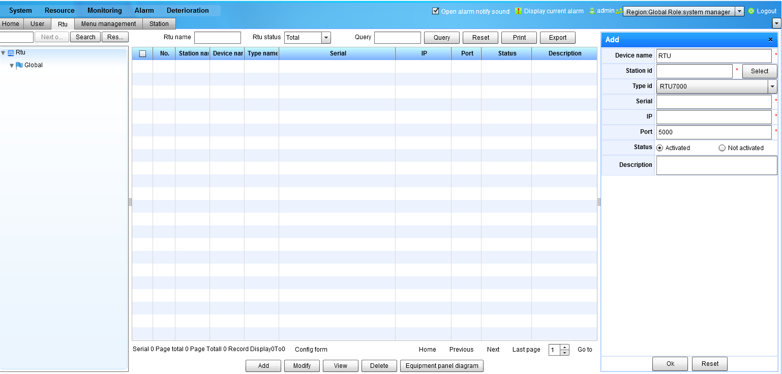
• RTU Management
●Manage fiber cable related properties, includes fiber ID, start/stop address project name, fiber cores, fiber type, fiber length …
●Manage monitoring center and site includes monitoring center/site ID, monitoring center/site name, constructor, contact information, property edit and modify…
●Maintain RTU
●Manage equipment and connection
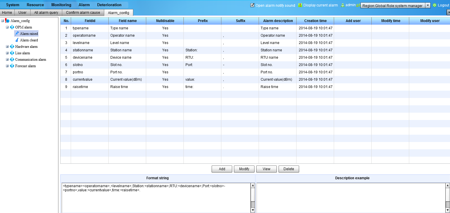
●Alarm Management
• Line Alarm Management
• Alarm Log
• SMS Alarm Log
• SMS Server Setting
• Default Alarm Parameter
●Locate fault on GIS and view detail alarm/SMS alarm information
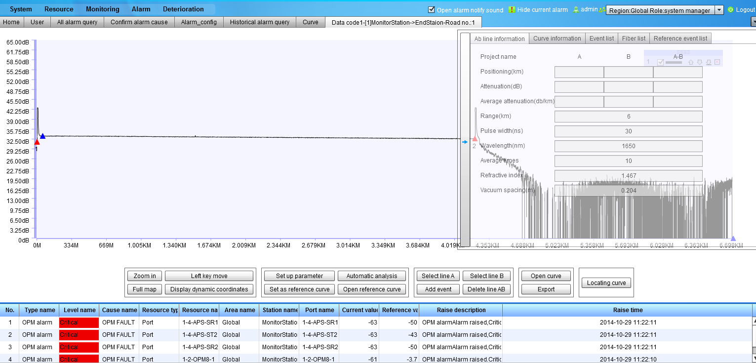
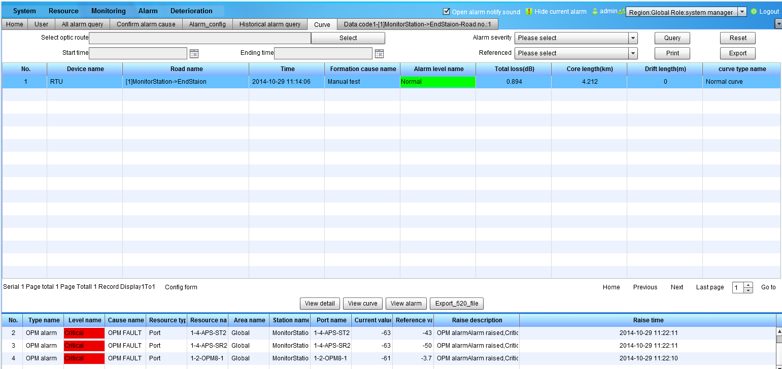
●Monitoring Management
• Curve Management
- Curve Information
- Reference Trace
- Threshold Setting
• Optical Switch Connection
• RTU Test
- Scheduled Test
- Manual Test
- Optimization Parameter
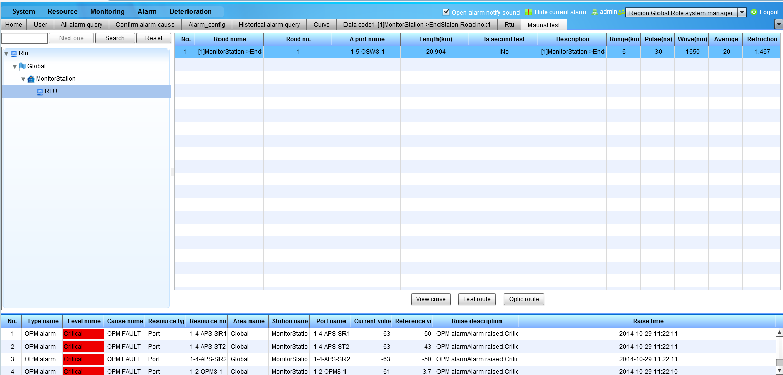
• Test Rote Management
- Download Test Rote
- Default Test Rote Parameter
ü Integrated GIS Map for OTDR Trace
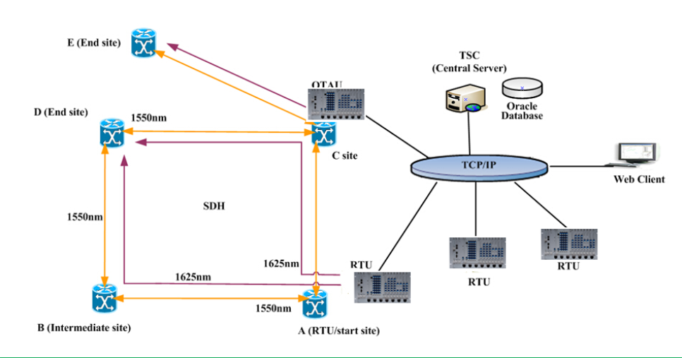
1.2.9 Scenario of Fiber Monitoring
Dark Fiber Monitoring (Out-Of-Service)
●Require one spare fiber
●Test wavelength can be the same to that of traffic
●Easy, safe, and lower cost
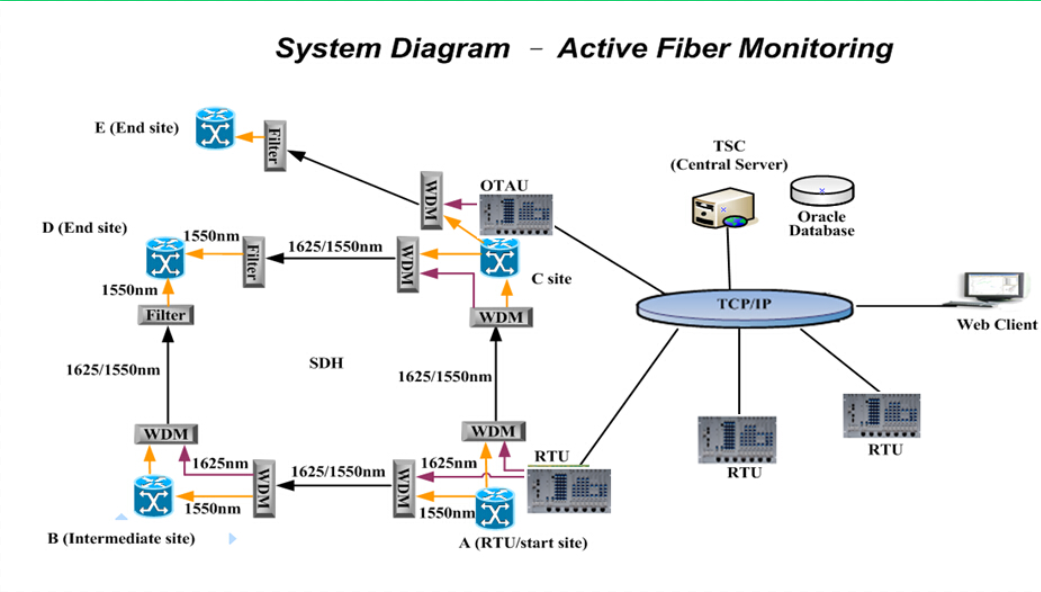
Active Fiber Monitoring (On-Service)
●Test fiber that carries live traffic
●Test wavelength is different to that of traffic
●WDM and filter required, implementation cost is higher
●Influence the transmission system while constructing
1.2.10 Customer Base
More than 20 operators of wireline and wireless networks successfully use the ShinewayTech products.
1.2.11 Conclusion
ShinewayTech customers have realized a positive impact of investment in FiberWatcher related to their revenue, operations cost and customer satisfaction. Our solution is established in many leading service providers. As SHINEWAYTECH continues to expand services with new markets and features, we are confident that you will realize the value of FiberWatcher and appreciate the impact it can have on improving your business.
2 Hardware Specification
Remote Test Unit (RTU) consists of the embedded Main control Unit (MCU), the Optical Time Domain Reflectometer Module (OTDR), the optical switch (OSW) and power unit (PWU) etc.
2.1 RTU(Remote Test Unit)

1) Running situation:
Environment Temperature: +10~+35℃;
Relative Humidity: <95% when 25℃
atmospheric pressure: 86 kpa~106 kpa;
Voltage: -48V DC±20%
2) Power Supply
Specified input voltage: -48V /DC
Permitted voltage range: -36V/DC~-72V/ DC
Power Consumption: Total consumption: <80W
3) Earthing
Communication Station: Combine ground, grounding resistance ≤1Ω,
intermediate stations: Grounding resistance ≤4Ω.
4) Weight : 13Kg
Size : 19” or 23” ; 19”x10.5”x11” (LxWxH)
2.2 OTDR
|
Wavelength (G.652 or G.655) |
1310 ±25 nm |
1550 ±25 nm |
1625 ±25 nm |
1310/1550 ±25nm |
|
Distance Range |
1/2.5/5/10/25/50/100/200/250/400 km |
|||
|
Pulse width |
10 ns ±30%, 30 ns ±25%, 100 ns ±10%, 300 ns ±10%, |
|||
|
Dynamic range (dB) |
41 |
40 |
43 |
39 |
|
Dead zone(back scattered light) |
≤20 m |
|||
|
Dead zone(Fresnel reflection) |
≤5 m (Typ. 2m) |
|||
|
Sampling resolution |
0.05 m to 80 m |
|||
|
IOR |
1.400000 to 1.699999 (in 0.000001 steps) |
|||
|
Distance measurement accuracy |
±1 m ±3 x Measurement distance x 10-5 ± Sampling resolution |
|||
|
Loss Measurement accuracy(linearity) |
±0.05 dB/dB or ±0.1 dB (whichever is greater) |
|||
|
Return loss measurement accuracy |
±4 Db |
|||
|
Laser safety specification |
21CFR Class 1, IEC Pub60825-1 Class 1 |
|||
|
Connector |
SC or LC |
|||
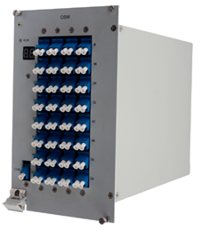
2.3 OSW
Optical Switch Unit
This OSW control card contains a microprocessor to control the light switch. The unit communicates with CPU MODULE with the backplane bus, support hot swap and multiple modules can be connected.
Specs:
Wavelength: 1.20~1.65um
Switch time: ≤25ms
Durability: ≥1 million times
Isolation: ≥60dB
Return loss: ≥45dB
Insert Loss: ≤0.5dB
Optical Connector type: LC/PC
Optical Ports.: from 4 to 64 according to the requirement
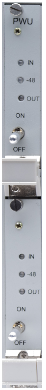
2.4 Power Unit (PWU)
Description:
Power supply module is designed to improve the reliability and stability, using stable power supply, overload protection and short circuit protection technologies. System equipped with two power supply panel provides system redundancy backup. It can support hot-swappable so it is easy to replace the board when the system is running. When the board is inserted, pull or power failures, the main control board can be notified. In addition, in order to protect the system security, we specially design the circuit protection to avoid the accidental damage due to poor power supply.
Specification:
Input voltage range: -36~-72V
Working temperature: 0°C~50°C
Humidity: ≦ 85 %
Dimension: 23cm x 27mm x 20cm
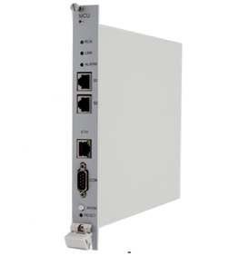
2.5 Main Control Unit (MCU)
Description:
The control module is used to manage and monitor the boards of monitoring station and communicate with the monitoring center server. To report the monitoring station’s status to the monitoring center station, or operate the orders issued by monitoring center. The embedded control systems have the advantages of structures refining, low power consumption, small size, flexible communication, data storage stability and easy maintenance.
Specs:
Internal Storage: 64M byte
Disk Storage: 64M byte
Processor Speed: 80MIPS
Working Humidity: 40°C/90%RH
Working Temperature: 0°C~50°C
Dimension: 23cmx 50mm x20cm
- Download
- Datasheet
- FiberWatcher Intelligent Optical Cable Network Monitoring and Management System-EN.pdf
-
No information

We will get back to you within 24 hours.